A dual-regime electromagnetic method for ground that stops ordinary radar
By: Leonid Krynytskyi — Founder & Principal Geophysicist, GPR Investigation
Most people first meet ground-penetrating radar as a shallow tool. Ordinary GPR works at high frequencies, listening for radio waves that bounce off the ground, and in dry, resistive terrain it does that beautifully. But much of Africa’s best exploration ground is anything but dry: conductive regolith, laterite, and saprolite, all of it swallowing a high-frequency signal within the first few metres. The ground most likely to host minerals is often the very ground that blinds a normal radar.
What we run is built for exactly that. It is a Horizontal Electric Dipole, Time-Domain Electromagnetic system, or HED-TEM, on the impulse Loza platform. Instead of treating the ground’s conductivity as the enemy, it leans on it.
One pulse – two stories
It makes more sense once you watch when the signal comes back, not just whether it does. One pulse goes in, and two different things happen to it.
The first arrivals behave like an echo. The pulse travels down, meets a contact or structure, and bounces back like a radar signal, except at low frequency, so the echo comes from hundreds of metres down, not the first few. That is the wave side.
What comes later is not an echo at all. The pulse stirs up electric currents inside anything conductive down there, from sulphides and banded iron to a weathered kimberlite or a water-bearing fracture, and those currents slowly bleed away, like a struck bell fading out. We read this late part of the record as a diffusion response, and it is what makes conductive bodies show up where a radar reflection would simply die. This is the diffusion side, and the real break from GPR: the kind of body that defeats ordinary radar is the kind that stands out here.
Pulling both out of a single record, echo early and slow fade late, is what sets this apart from plain GPR and from standard loop-TEM.
The time and depth
The source is nothing exotic: a pair of resistively loaded dipole antennas laid out along the line, not the wire loop a standard TEM system uses. Length sets the frequency, and frequency is the trade-off between depth and detail. Stretch the antennas out, and you drop to lower frequencies that punch deeper but paint with a broader brush; keep them short, and you stay high, sharp and shallow. As a rule of thumb, 6 m of antenna sits near 25 MHz for detail, 10 m near 15 MHz for depth. A receiver records the whole returning signal along the line, trace by trace (Figure 1); lay the lines on a grid, and they knit into a full 3D block.
That recording is in time, and turning it into depth is the real work. After each pulse the receiver keeps listening for a few thousand nanoseconds; a longer window simply gives us more of the late response to follow, and reading it as depth takes an interpretation, not just a longer recording. On the Botswana section the time base runs to about 4,096 ns, which the interpretation ties to roughly 200 m (Figure 2). How far we can follow a feature in the end comes down to the ground: in resistive terrain the useful signal reaches well past several hundred metres, while conductive cover shortens that reach, so over the more conductive ground where most ore sits we usually hold a clean signal to 150 to 300 m.
What it actually shows
Figure 2 is a kimberlite pipe in Botswana. You can read the classic carrot straight off the image, a wide crater up top pinching into a narrow root, and follow it to the base of the 200 m section. Weathered kimberlite turns to conductive clay, exactly the sort of body the late-time signal picks out against a quiet, resistive background.
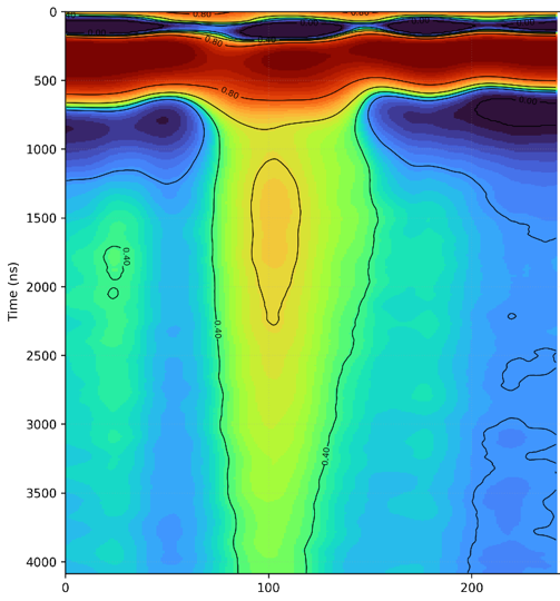
Figure 2. Kimberlite pipe, Botswana — a slice through the amplitude volume. The vertical axis is recording time in nanoseconds; the classic carrot shape runs from below the near-surface cover down to an interpreted depth of about 200 m (time base to roughly 4,096 ns).
The targets need not be ore. Figure 3 is a water traverse over a carbonate aquifer in Zambia. The sections picked out the fractured, faulted ground that carries water, including a fault zone some 200 m across that the geological map later confirmed; boreholes drilled onto those anomalies struck water near 25 m, with blow yields of 12.5 and 10 litres per second. The drill was the referee here, and it agreed.
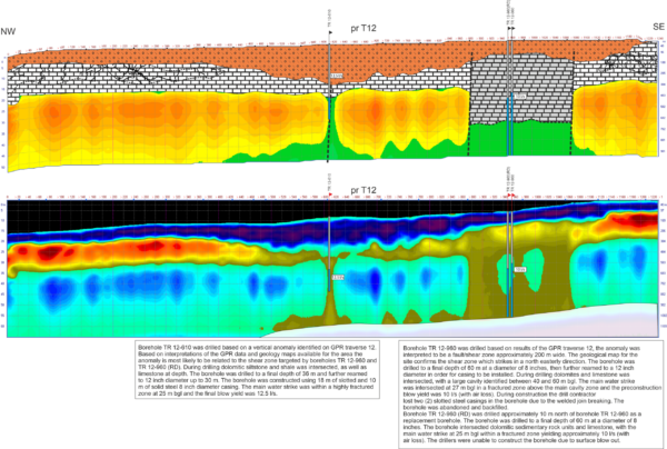
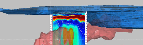
Figure 4 is the one I would point a sceptic to, an ore-hosting body in Namibia. We interpreted the HED-TEM section on its own, from the physics, and only then set it beside the client’s own Leapfrog model, the one their geologists built from drilling. The anomaly contours match the body in that model, point for point, in precisely the conductive ground this method was made for.
Where it fits, and where it does not
Every method has limits, and this one is no exception. It points the drill rather than replaces it; the assays still come from core. Resolution falls with depth, so you map zones and structures, not thin veins far down. Thick conductive cover restricts penetration, mine infrastructure adds noise, and different materials can give similar responses, so the local geology stays part of every interpretation.
It earns its keep between first reconnaissance and a drill plan: conductive targets like sulphides in greenstone belts, mineralised reefs, kimberlite and graphite, plus structure and groundwater. For explorers working in Zambia, the DRC and the rest of southern Africa, where the ground is promising but rarely cooperative, a method that gets stronger on the very bodies that defeat an ordinary radar is worth a serious look.
About GPR Investigation
GPR Investigation is a Czech-based geophysical consultancy built around deep HED-TEM electromagnetic surveying with the impulse Loza system. Over roughly 20 years, we have run surveys on mineral, groundwater, and infrastructure projects in 63 countries across five continents, helping explorers find and rank drill targets under conductive cover that stops conventional methods.